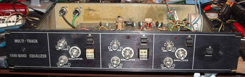
 The Multi-Track Vari-Band Parametric Equalizer before restoration
 Some gear, because of it pedigree and the esteemed place it has earned in the hearts and minds of engineers earns the title "Vintage." Other gear is just plain old. So, where does one draw the line between vintage and just plain old?
The piece of gear that seems to be balanced right on the dividing line between "vintage" and "just plain old", ready to tip to one side or the other at any moment is a parametric equalizer called the "Multi-Track Vari-Band." Apparently, this piece of gear was manufactured in the early to mid seventies by the Multi-Track company, purportedly located in North Hollywood, California. There is basically no documentation available anywhere on the Internet about this piece or the company that made it. In fact, the only place I've ever seen anything even resembling this piece (before the Ebay auction where I was lucky enough to snag two non-functional units) was in a John Woram's 1979 book entitled "The Recording Studio Handbook, Second Edition." In the chapter on equalizers there is a picture of a five-band Multi-Track Vari-Band EQ with caption "Orban 622", which it obviously wasn't.
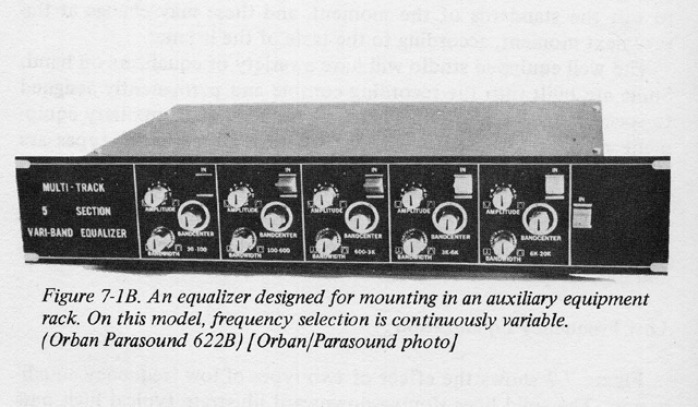
A scan from The Recording Studio Handbook 2nd Ed. by John Woram, published in 1979 Back in July of 2005 I stumbled on an Ebay auction for two, three-band EQs that were obviously in need of lots of TLC. But they were so cool looking I just had to have them, even if they never served any better purpose than to fill empty spaces in my rack. Lucky for me, I was able to restore one of them to its original luster. Here's the story:
At the beginning of this project, the reason I was unsure whether these units were "vintage" or "just plain old" was because of the build quality. It was like the original designers were schizophrenic when it came to gear design. It appears that they attempted to use very high quality parts throughout the unit except for the power supply bypass capacitors, which appeared to be the absolute cheapest crap they could find. And the circuit boards appeared to be substandard as well. They were obviously laid out by hand, using Letratset-style dry transfers for the pads and traces. Forget about silkscreening, plated through-holes and solder masks. I also noticed that all the wires running from the front panel controls to the circuit board criss-crossed each other. Apparently, the designers didn't realize that the foil side of the board would actually face down when installed in the unit, so they laid the board out as a mirror image of the way it should optimally be. My first thought was to flip the board and mount it in the case with the foil side facing up. I later realised all I have to do is flip the front panel over and mount the case "upside down". I could eliminate about 50% of the wiring by doing this. Maybe later.
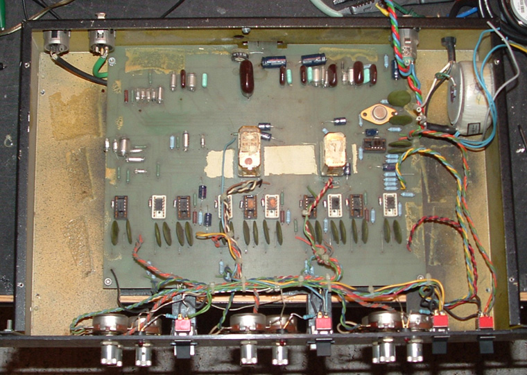 A look at the inside of the unit before restoration
 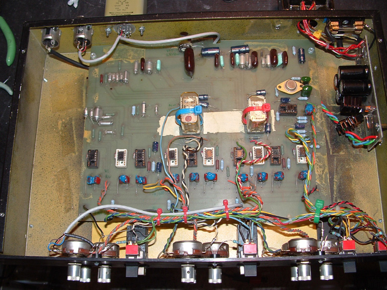 A look at the inside of the unit after restoration
 So, where do you start with a piece of gear that you have absolutely no documentation on? Add to that, the manufacturer sanded the numbers off all the chips so I didn't even have part numbers to go by. It looks like the two units were originally powered by a common, external power supply of some sort. The two units were supposed to be connected together by edge connectors that were a part of the circuit board. Someone had obviously made a feeble attempt at reviving these units and attempted to put a bipolar power supply in one of them, connecting the two together via 4 pin XLR connectors. The power supply board they used was obviously a part of some other piece of gear at one time, and they just took a hacksaw and cut the power supply portion of the board away and stuck it inside the chassis of one of the units. This was going to be fun restoration because it would be a challenge.
I started by snipping all the wire ties and tracing the connections to all the front panel controls. This showed me which areas of the circuit board served which functions - low, mid and high bands, and output amp. I labeled the connections at each point on the board. After identifying the various portions of the circuit I connected the unit to my bipolar bench power supply, HP Audio Analyzer and oscilloscope. I then started looking at waveforms at various points on the board, mainly the inputs and outputs of all the op amps. Even though the designers thought they were being tricky by sanding all the numbers off the chips, almost all 8 pin DIP packaged op amps have the same pin out so taking measurements was easy. The waveforms I saw were ugly. Lots of noise, obvious clipping and distortion, and no consistency anywhere in the circuit.
Since most of the components were decent quality, and somebody before me had replaced all of the electrolytic caps with Panasonic HF series, I made the assumption that most of the noise was coming from poor connections, either in the form of cold solder joints or dirty contacts at the sockets. So, the first thing I did was to remove all the op amps and clean the sockets and chip pins with my favorite zero-residue cleaner. After doing this the unit showed little or no improvement so the next step was to "freshen" solder joints on the board. As gear ages, the solder joints on the board oxidize, causing high resistance and intermittent connections. By simply reheating the connections and adding a little new solder, good electrical contact can easily be restored. I've worked on many pieces of gear where this is all that was needed. In the case of the Vari-Band EQ, there were two relays used to change the frequency bands of the low and mid sections, and the connections at the PC board had obviously become loose due to someone reseating the relays too many times, with too much force. Freshening the solder points on the PC board caused the relays to start working properly but still didn't get rid of the noise and distortion in the unit.
While freshening connections on the board I noticed that the waveform cleaned up when I jiggled the 4-pin XLR connector on the rear panel that was used to supply power to the unit. Further inspection revealed an intermittent ground connection here. I removed the connector altogether and soldered the power supply connections directly to the circuit board. This cured some of the clipping and symmetry issues in the waveform but not the noise and stability. The unit was still not behaving consistently when I switched the EQ bands in and out of the circuit, and when I swept the frequency, bandwidth and slope controls. So, on I trudged, hoping I could get this thing working at least well enough to justify the considerable amount of time I had now invested in the unit.
As I mentioned earlier, this unit had really cheap, terrible ceramic capacitors in it, used to bypass each op amp's power supply connections to ground. Power supply bypassing is standard procedure in modern gear but I had never seen such crappy capacitors used for this purpose. The capacitors in this unit were .1 uF, 20 Volt ceramics. I would have chosen a voltage rating of at least 50 volts. So, the next step was to replace all 22 crappy ceramic caps with .1 uF, 50V polypropylene film units left over from my GSSL project. Even though replacing these caps made me feel much better about the long-term prospects of the unit it did nothing to reduce the noise, nor to stabilize the operation of the unit.
At this point I began to wonder about my tech skills and also whether this unit justified the amount of time and effort I was spending on it. Still, I trudged on by continuing to inspect the physical layout of the board. I suspected there was a bad connection somewhere that just needed to be resoldered. I finally found it while poking at the connections on the front panel controls. At first it appeared to be one of the connections on the low frequency amplitude pot so I replaced the wires leading from that pot to the circuit board with shielded Mogami quad-core cable. No change. But I noticed that next to that wire there was a single ground connection leading from all the controls on the front panel to the circuit board. Bingo! Upon inspection of the point where that wire connected to the board I noticed that this wire had been pulled on so many times it had come completely loose. As soon as I soldered that connection at the board the unit became completely stable and dead quiet. Distortion dropped to 0.011% and noise was down below -90 dBm. Success!
Now that the unit was completely functional I turned my attention toward putting an internal power supply into it. Up until now I had been powering it from my bench power supply. Someone had put a decent-looking toroidal transformer in the unit but no line fuse or other means of protection. I tested the transformer and found it to be a 75V center-tapped unit, which was too much voltage for this application, in my humble opinion. When I pulled the transformer I noticed that is was a custom unit built for Purple Audio, presumably for use in their 1176 clones. So, as luck would have it, I got a little bonus out of this deal - a toroidal 1176 power transformer! Sweet!
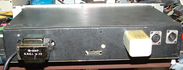 The rear panel of the restored unit, showing the Urei power transformer and Triad HS-56 input transformer
 While looking through my rather generous power transformer stash I found one out of an old Urei 527 EQ that would be perfect for this unit. I mounted it on the back where the XLR connector used to be, and added an internal fuse holder for protection against fires, should something in the unit short out and start drawing way too much current. I also added added a 15 volt, regulated bipolar supply out of an old compressor project I did about 10 years ago. As a finishing touch I replaced all of the old, very early (vintage?) red LEDs with new, blue units. I also added an LED above the main IN/OUT switch to indicate when the unit was in the circuit. The finishing touch was to add a Triad HS-56 transformer to the input, to make it truly balanced. The unit was originally wired with pin 3 shorted to ground, which can damage some actively balanced gear.
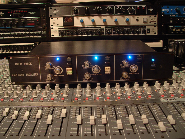 Finally! Using the unit on a mix. Sounds great on drums, bass, guitar, vocals.
 The time had finally come to hook this baby up and try it on a mix. This also answered the question as to whether this unit was "vintage" or "just plain old". After listening to it and playing with it I'd have to say this unit definitely earns the title "vintage". It's clean, quiet, versatile, and does exactly what a good parametric EQ should do. I found the designer's choice of frequency ranges to be very useful, especially the 20-100 Hz low band setting. I can't wait to get the second unit restored and in the rack. If you ever run across one of these units or the five-band version, definitely snatch it up. They're well worth restoring and great conversation pieces!